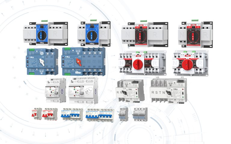
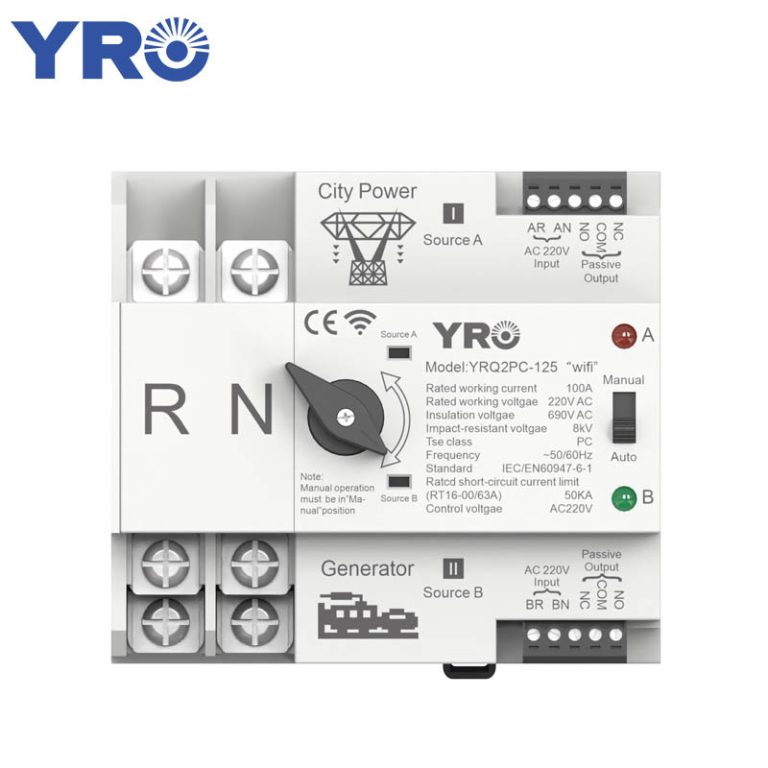
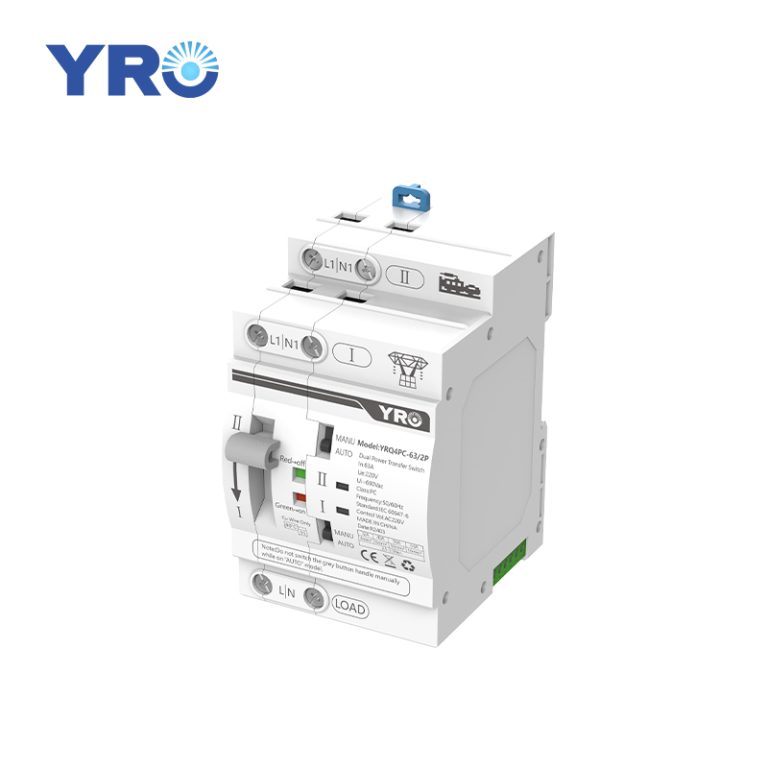
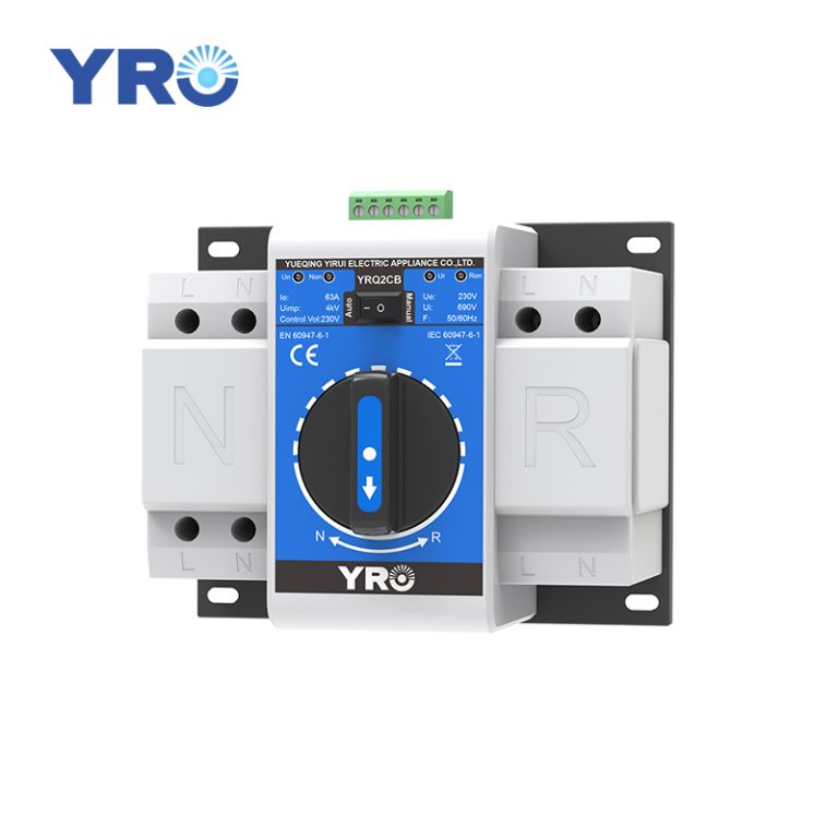
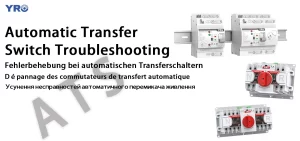
Automatic transfer switches (ATS) are critical components in backup power systems, ensuring seamless transitions between primary and secondary power sources. When they malfunction, the consequences can range from inconvenient to catastrophic. Understanding how to systematically troubleshoot ATS issues can save you time, money, and prevent dangerous situations. Below we outline the most common ATS problems and step-by-step solutions.
Identifying Common ATS Symptoms
Recognizing the specific symptom your ATS exhibits is the first step toward resolution. Here are the most frequent issues:
1、Power Loss or Controller Unresponsiveness
When your ATS shows no signs of life – no lights, no display, no operation – the problem often relates to power delivery. This could be caused by:
- Tripped input breakers or blown fuses
- Loose wiring connections at terminal points
- Wiring error
- Faulty controller power supply components(The controller is the core component of the ATS. It is responsible for monitoring the power supply quality of the two power sources in real time, and issuing instructions to switch the power sources.)
2、Failure to Transfer Power Sources
The controller appears functional (lights are on), but the switch refuses to transfer between power sources despite outages. Common culprits include:
- Incorrect mode selection (manual vs. automatic)
- Improperly configured operation modes (self-reverting vs. maintained)
- Undervoltage settings that don’t match the actual power conditions
3、Tripped Indicators or Physical Damage
Visible trip indicators or physical signs like discoloration or burning smell require immediate attention. Causes include:
- Short circuits in downstream equipment
- Overload conditions exceeding ATS ratings
- Contact welding due to frequent operation under load
Critical note: Never attempt manual transfer without first resolving the cause of the trip, as it risks equipment damage and personnel injury.
Step-by-Step Troubleshooting Guide
Follow this systematic approach to diagnose and resolve ATS issues safely:
Step1:Safety First
Disconnect the main power supply and the backup power supply, and use a multimeter to confirm the power-off status. Place warning tags at disconnects points.
Step2:Visual Inspection
Examine for obvious physical damage: burned components, loose wires, water intrusion, or corrosion. Check terminal tightness (torque to manufacturer specifications) and ensure proper wire stripping without nicks.
Step3:Controller Diagnostics
Re-energize only the control circuit. Check indicators against manual interpretation. Verify settings (voltage thresholds, timers, operation mode). Test voltage sensors with multimeter.
Step4:Manual Operation Test
The movement should be smooth without any lag. If resistance is encountered, it may be due to gear wear or bearing jamming. Check for mechanical obstacles or problems with the interlocking device.
Step5:Power Source Simulation
Safely simulate power failures by disconnecting primary source. Time the transfer sequence. Repeat for retransfer upon restoration. Compare timing against specifications.
Step6:Connection Integrity Check
Inspect plugs and connectors between controller and switch mechanism. Reseat connections. Test continuity on critical signal paths.
PC-Level vs. CB-Level ATS: Troubleshooting Differences
Understanding your ATS type is crucial for effective troubleshooting:
| Symptom | PC-Level ATS Approach | CB-Level ATS Approach |
| Tripped Position | Not applicable (no trip mechanism) | Check MCCB trip history; investigate short circuits or overloads |
| Contact Failure | Inspect for welding; test contact resistance | Check both mechanism and breaker contacts; test breaker closing function |
| Short Circuit Response | Verify upstream protection device operation | Test integrated breaker trip settings and timing |
| Overload Handling | Confirm sizing | Evaluate breaker trip settings match load profile |
| Transfer Mechanism Issues | Focus on motor/coil drive systems | Check mechanical interlocks between breakers |
When to Call a Professional
While many ATS issues can be resolved with systematic troubleshooting, these situations warrant professional assistance:
- Evidence of internal arcing or component melting
- Repeated tripping without identifiable cause
- High-current systems where specialized equipment is needed for testing
For CB-level systems, certified electricians should verify proper coordination with upstream/downstream protective devices
Preventive Measures to Avoid Future Failures
- Regular Maintenance Schedule
Implement semi-annual inspections even without apparent issues. Include:
- Terminal tightening to specified torque values
- Insulation resistance testing
- Contact resistance measurement
- Environmental Protection
Install in clean, dry locations away from excessive vibration.
- Voltage Monitoring
Set voltage thresholds appropriately (typically±10% of nominal). Avoid settings that cause nuisance transfers but allow harmful under-voltage operation.
Conclusion
Effective ATS troubleshooting requires understanding both the electrical and mechanical aspects of your specific transfer switch. By recognizing common symptoms, methodically testing components, and knowing the differences between PC-level and CB-level systems, you can resolve most operational issues efficiently. Regular preventive maintenance remains the best strategy against unexpected failures. When in doubt or faced with complex electrical faults, partner with qualified professionals to ensure your backup power system maintains reliability when you need it most.
Equipped with over a decade of hands‑on manufacturing experience and complete OEM capabilities, YRO delivers robust, field‑tested ATS units tailored for solar, generator, and hybrid power systems.

